A dimension is stated as Dia 25 H7 in a drawing. The lower limit is 25.00 mm.
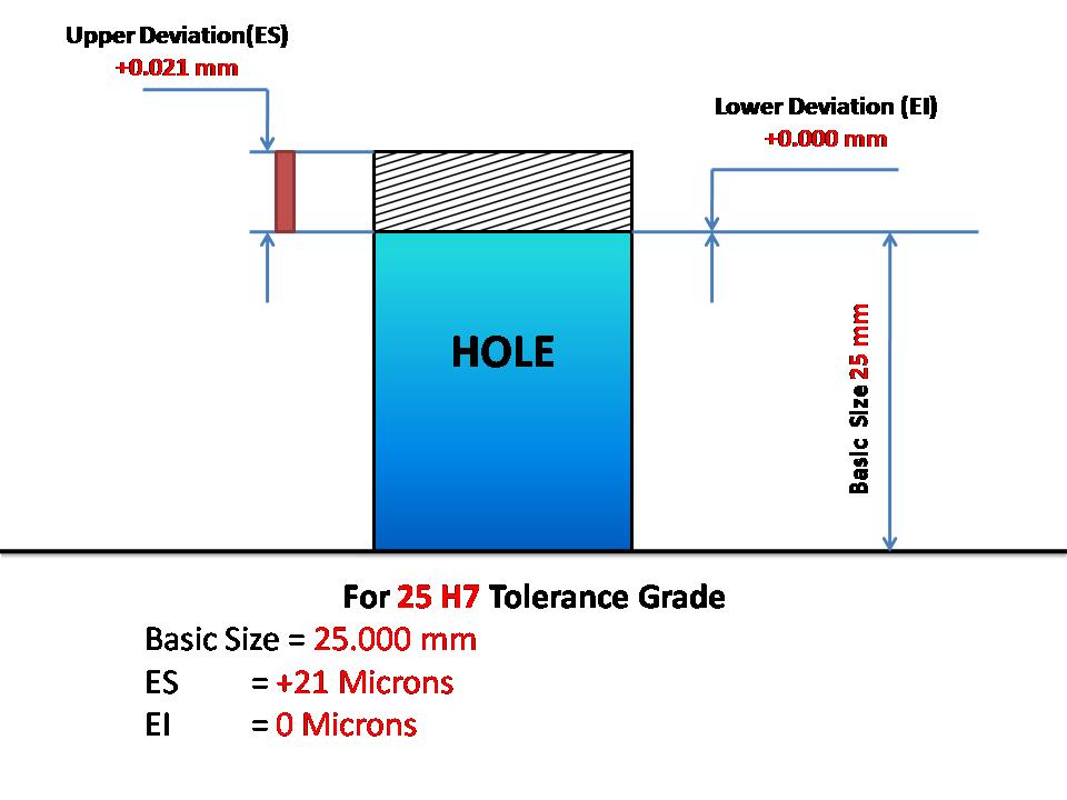
For 25 H7 Tolerance Grade
Basic Size = 25.000 mm
ES = +21 Microns = 0.021 mm
EI = 0 Microns = 0.000 mm
Hence
Lower limit = Basic Size + EI = 25.000 + 0.000 = 25.000 mm
Upper Limit = Basic Size + ES = 25.000 + 0.021 = 25.021 mm
Hence A dimension is stated as Dia 25 H7 in a drawing. The lower limit is 25.000 mm.
4) A dimension is stated as Dia 25 H7 in a drawing. The lower limit is ?
25.00 mm

Related Limits and Fits MCQ - Machinist(Set-1) with Answers
0.04 mm
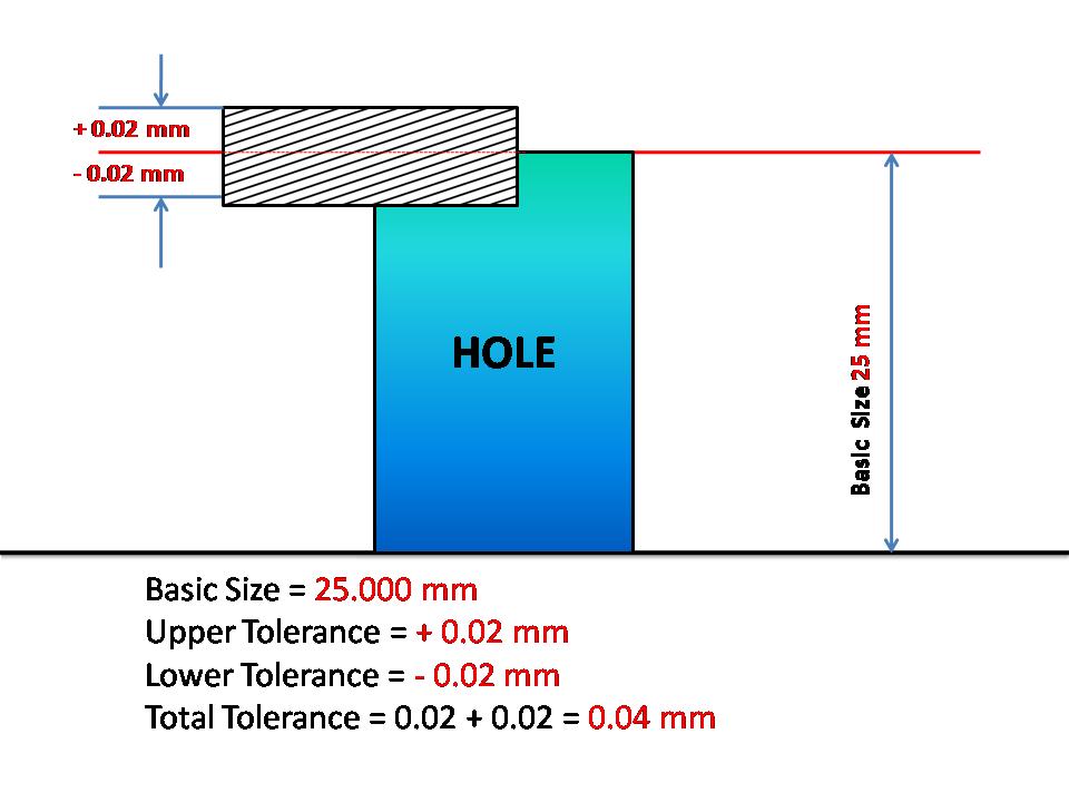
A dimension is stated as 25 +/-0.02 mm in a drawing. Then
Basic Size = 25.000 mm
Upper Tolerance = + 0.02 mm
Lower Tolerance = - 0.02 mm
Total Tolerance = 0.02 + 0.02 = 0.04 mm

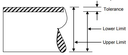
Tolerance
Tolerance is defined as the difference between the maximum and the minimum sizes allowed in manufactured components.

Actual size
The measured size of the dimension of a component is called Actual size.
Interference fit
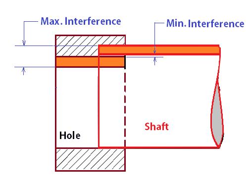
If the tolerance zone of the pin is entirely above of that hole, then the fit obtained is called as interference fit.
Interference Fit Interference fit is defined as the fit established when a negative clearance exists between the sizes of the holes and the shaft. In Interference fit, the minimum permitted diameter of the shaft is larger than the maximum allowable diameter of the hole.
Examples for Interference Fit are: Bearing bushes, small end in the connecting rod.
